Minimised AGV apron. An alternative approach to waterside operations.
Automatic guided vehicles (AGVs) are a proven automated transport system for container terminals. Since the introduction in 1993 at ECT in the Port of Rotterdam, AGVs have been used at more than 10 sites across the world. At this time, AGVs are there with the most successful automated transport system in container terminals. AGVs are reliable and can support high Quay Crane (QC) productivities . In addition, battery AGVs have been available since 2012, supporting zero-emission terminals. Overall, AGVs are a solid and proven solution for terminal automation. However, an AGV operation requires significant space on the apron, especially compared to existing terminals with manned vehicles. As terminals are often space constrained, any space that can be saved on the apron directly translates into additional yard capacity.
This article describes an alternative approach for the interchange between QC and AGV at a similar footprint as for terminals with manned vehicles.
Figure 1 shows a typical cross-section of a container terminal with perpendicular (to the quay) Automated Stacking Cranes (ASC) and AGVs. Existing AGV terminals have similar apron designs, showing an apron width in the range of 120 to 130 metres, measured from the landside QC rail to the first container in the yard. For safety purposes, the AGV operation is typically in the back reach of the QC, separated by a fence from the area where humans are allowed. In addition, most sites use double trolley QCs, i.e. a waterside trolley that moves containers between the vessel and the twistlock platform in the QC and a second landside trolley moving containers between the twistlock platform and AGVs.
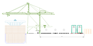
Figure 1: Typical cross section of AGV terminal with ASCs
The 125 metres wide AGV apron can be split into four areas. From left to right (Figure 1):
- QC interchange area (7 lanes): for AGV – QC interchange and AGV bypass (to allow for AGVs to access adjacent QCs).
- Perpendicular buffer: waiting location for AGVs before accessing QC lanes or before entering a highway.
- AGV highways (6 lanes) for transport along the quay to/ from ASC modules in the yard.
- ASC interchange area: for AGV – ASC interchange.
A significant part (approximately 25 metres) of the 125-metre AGV apron is the perpendicular buffer. This buffer is a key contributor to an increased QC performance that AGV terminals can support. This buffer allows AGVs to wait close to the QC without blocking other AGV traffic, ensuring smooth traffic on the highways and a timely arrival at the QC, as well as the ability to deal with out-of-sequence arrivals. Simulations have shown that without this buffer, high QC productivities cannot be supported (due to AGVs waiting far away and traffic congestion). This is not only true for AGV terminals, but also for terminals with other types of automated horizontal transport.
To reduce the apron width at AGV terminals, an alternative approach is explored where the perpendicular buffer is not only used as buffer, but also as QC interchange lanes, i.e. eliminating the separate interchange lanes in the original AGV layout, see Figure 2. With this arrangement, the apron width can be reduced to approximately 96 metres. This does require the QC to have the capability to rotate the container. Therefore, a double trolley QC is required where the secondary trolley (the trolley between twistlock platform and AGV) can rotate the container.
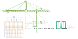
Figure 2: Proposed cross section of ASC terminal with AGVs
Figure 3 shows the alternative approach next to the “traditional” AGV apron. The difference between the two alternatives can clearly be seen. The reduction in apron width can be directly translated into longer ASC modules with an additional length of about 4 to 5 TEU. Depending on the length of the ASC modules, this could mean an increase of about 10 – 12.5 per cent storage capacity (based on 40 TEU ASC blocks – typical block lengths vary from 30 to 50 TEU).
Another benefit of the narrow AGV apron is the operation in a dense QC cluster. Figure 3 shows a cluster with 5 QCs. In the traditional AGV layout (left), AGVs wait on one side of the cluster and drive to the crane when needed. To reach the last crane (5th), the AGV must pass four other QCs. This results in dense traffic. In the alternative approach, each QC is directly accessible from the highways, i.e. there is no interference with traffic for the other QCs.
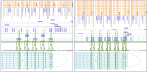
Figure 3: Top view of current AGV layout (left) vs. proposed minimised AGV layout (right)
Each QC has access to three dedicated interchange lanes, allowing buffering up to three AGVs per QC. If needed, more AGVs can wait in the vicinity of the QC as there are more lanes available, although without direct access to the QC. When a lane at the QC becomes available, the AGV can drive to the interchange lane.
The grid of buffer/ interchange lanes is fixed. Figure 4 shows the arrangement under the QC, for a cluster of three QCs. Each QC always has access to three lanes in the interchange grid. In between two QCs, three to four additional lanes can be used as temporary buffer lanes if all three interchange lanes are fully occupied.
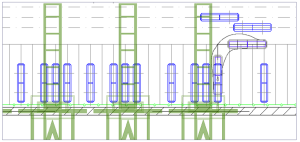
Figure 4: Zoom-in top view proposed narrow AGV layout
Impact on QC
To enable the proposed narrow apron, containers need to be rotated 90 degrees by the QC. Existing QCs cannot rotate containers. At first glance, this seems a serious obstacle. However, because most AGV sites use double-trolley QCs, the impact of modifying the QCs will not be that big. There is no change needed for the main hoist, i.e. the move between vessel and twistlock platform remains the same as today. The secondary trolley (moving between platform and AGV) needs additional functionality.
In essence, the secondary trolley is nothing more than an overhead bridge crane moving up and down the beams of the crane. To support the narrow AGV apron, two additional functionalities are required:
- Rotation of the container by 90 degrees.
- Sideways movement to reach all of the three transfer points dedicated to that quay crane.
Both functionalities are available in overhead bridge cranes today, and rotation of containers is common practice in wide-span intermodal (rail head) cranes.
An initial conceptual design of the secondary trolley shows the feasibility of creating sufficient freedom of movement of the secondary trolley to support three interchange lanes at all times. Figure 5 shows a 3D impression of the secondary trolley. The image shows the sideways movement of the trolley, as well as the rotation.
Similar cycles times are expected in terms of performance to the existing double trolley QCs. The sideways movement and rotation can be performed during the travel movement of the second trolley, and in general, the second trolley movements to the AGV interchange lanes are shorter.
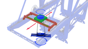
Figure 5: 3D impression of landside trolley with sideways movement and rotation
The design also has a provision for one exception interchange position. This is a parallel AGV position directly behind the 3 perpendicular interchange positions (see Figure 6). This position allows for the main trolley, which cannot rotate, to place a container directly onto an AGV. This could be needed in specific cases. For example, certain tank containers cannot be placed on the twistlock platform. It can also be used in case the second trolley is out of service (rather seldom), although that would result in a significant reduction of the crane’s performance.
Additional benefits
The main benefit of this concept is the reduced apron width which provides more space for container storage (more than 10 per cent). On top of that increase in storage capacity, this alternative approach provides additional benefits:
- Shorter AGV driving distances compared to traditional AGV terminals as the AGVs drive to the interchange lanes locations (with buffer capability) only.
- There is no need to drive through a traffic-dense area around a cluster QCs.
- In the traditional AGV terminal design, AGVs regularly need to make special correction moves to achieve the correct container door direction. This is not needed in the proposed approach, as containers are rotated by the second trolley of the QCs.
- Each QC has its own three interchange lanes, supporting dense QC clusters without a loss of QC performance from AGV traffic congestion.
Figure 6: Exception lane for containers that cannot be handled with the second trolley
Application of the concept
The proposed concept can be used for both greenfield and brownfield applications. All new equipment, including QCs, needs to be acquired for greenfield sites. Depending on the available space, one could choose the traditional arrangement (when space is not an issue), use the proposed arrangement to allow for at least 10 per cent more yard capacity or operate on a smaller footprint. Selecting the appropriate QCs can be part of the design process.
For brownfield sites, the choice is less straightforward. Space-wise, the same considerations apply as the greenfield sites, but – generally – one can expect space to be limited. Hence, the proposed alternative approach provides benefits. The main challenge is that the existing QCs are often single-trolley QCs that cannot rotate containers. As the existing QCs are often not “end of life”, early replacement requires significant CAPEX and is consequently undesirable. Therefore, the arrangement should also work with existing single-trolley QCs.
To support brownfield operation with the new approach, AGV interchange could take place within the gauge of the QC. The interchange lanes are now used as a perpendicular buffer (similar to the traditional AGV layout) for the purpose of waiting, staging, buffering, etc. When the QC is end of life, it can be replaced by a double trolley QC, and operations can be fully moved to back-reach operation (berth by berth) based on the proposed approach.
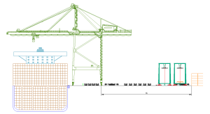
Figure 7: In gauge operation with single trolley quay cranes
Concluding remarks
Based on an initial evaluation of an alternative approach to the container interchange of between QCs and ASCs with an AGV transport system, the required apron “depth” to accommodate for AGVs can be reduced from 125m to 96m. This space reduction can be translated into more than 10% extra storage capacity. Alternatively, this space reduction may make it possible to consider implementing AGVs at existing terminals with manned vehicles.
Another outcome of the initial evaluation is that the required design modification to a double trolley QC seems technically feasible, as all required functionalities are available from intermodal rail cranes.
The following steps are recommended to further validate the concept:
- Further investigate the double trolley QC design (feasibility, loads, etc).
- Verify the operational feasibility in terms of performance and traffic through detailed simulation analyses.
- Evaluate whether the proposed concept can also work for other types of horizontal transport like automated shuttle carriers.
- Assess impact on the Terminal Operating System (TOS) and Equipment Control System (ECS).